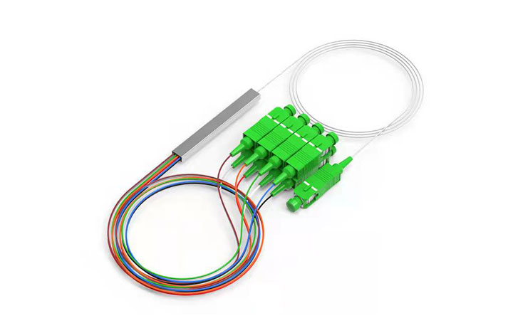
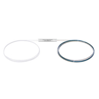
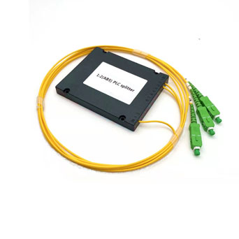
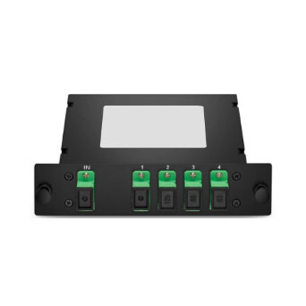
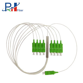
A planar lightwave line (PLC) splitter is a device that splits an optical signal into multiple outputs. The following are the key steps in the design of plc splitter fabrication:
Substrate Preparation
Silicon dioxide (SiO₂) wafers as a substrate material is preferred for its excellent optical properties and compatibility with lightwave circuits.
Waveguide Fabrication
A waveguide pattern is formed on the substrate using photolithography. First, a layer of photoresist is coated on the wafer surface, followed by exposure of ultraviolet (UV) light to the desired area through a mask and removal of the unprotected portion to form the waveguide path using wet or dry etching techniques.
Refractive index tuning and waveguide optimization
Waveguide materials are doped to adjust the refractive index of the waveguide core and cladding to optimize the optical signal propagation performance. In addition, the waveguide structure is stabilized by heat treatment (annealing) to reduce internal stresses and improve optical performance.
Beamsplitter Structure Design and Manufacturing
Splitter structures are designed according to requirements to ensure that optical signals are distributed in a predetermined ratio by precisely controlling the length and width of the waveguide. This step determines the split ratio and overall performance of the splitter.
Encapsulation and fiber connection
The input and output optical fibers are precisely aligned with the waveguide and secured, usually using high-precision automated equipment. The splitter chip is then encapsulated in a compact protective casing to protect it from moisture and dust and to ensure long-term stability. Fiber optic connection ports (e.g. SC or LC interfaces) are also installed at this stage for integration with fiber optic network systems.
Testing and Calibration
The finished PLC splitter is rigorously tested to evaluate key performance indicators such as insertion loss, split ratio, return loss and uniformity. Calibration ensures that the equipment performance meets industry standards and customer requirements.
PLC splitters use silica-based waveguide technology for uniform signal splitting, ideal for high split ratios (1x16, 1x32, etc.). FBT splitters, on the other hand, use fused biconic taper technology and are better for low split ratios (e.g., 1x2, 1x4).
FTTH Networks: PLC splitters are deployed in FTTH networks to distribute optical signals from a single optical line terminal (OLT) to multiple optical network terminals (ONTs) in homes or businesses.
PON Systems: In passive optical networks (PONs), PLC splitters are crucial components for splitting optical signals to serve many subscribers.
Data Centers: PLC splitters are used in data centers to ensure efficient optical signal dispersion and communication.
CATV Networks: CATV systems use PLC splitters to distribute optical signals to different houses.
A PLC (Planar Lightwave Circuit) splitter distributes optical signals equally from an input fiber to several output fibers. It uses waveguides engraved onto a silicon chip to route and split light with little loss. The waveguide design determines the splitting ratio (for example, 1x2, 1x4, 1x8), resulting in efficient and exact signal distribution over all outputs.

 EN
EN

