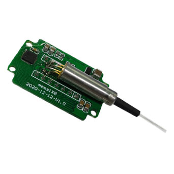
Main Specifications of MEMS 1xN(2≤N≤48) Optical Switch Module
Parameters | Unit | Value |
Number of channels | CH | 2 | 4 | 8 | 12 | 16 | 24 | 32 | 48 |
Wavelength | nm | 1310±20 or 1550±20 or 1625±20 |
Insertion Loss(Max) | dB | 0.5 | 0.7 | 0.8 | 1 | 1 | 1.2 | 1.4 | 1.5 |
Return Loss | dB | ≥50 |
Repeatability | dB | 0.03dB Max |
Crosstalk | dB | ≥50 |
PDL | dB | ≤0.15 |
WDL | dB | ≤0.3@CWL±20nm,23℃ |
TDL | dB | <0.4dB |
Operation Temperature | ℃ | -5~70 |
Storage Temperature | ℃ | -40~85 |
Switch Time | ms | ≤30 |
Durability | cycle | ≥1×10^9 |
Control Voltage | V | 5 ~ 12 |
Note: 1. The above test loss (IL) is based on the test results at 23 ℃ at the central wavelength ± 20nm;
2. Repeatability is defined after 100 cycles.
3. Excluding the connector, the insertion loss of the connector is increased by 0.2dB.
4. IL is for single-band. Dual-band adds 0.3 dB.
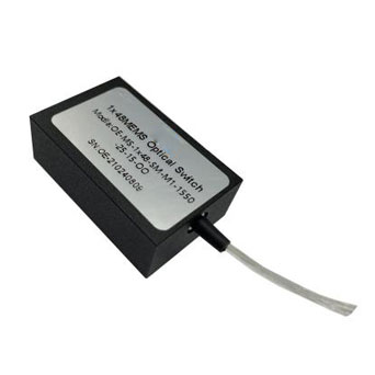
Dimension(MEMS 1x2/4/8 Optical Switch) of MEMS 1xN(2≤N≤48) Optical Switch Module
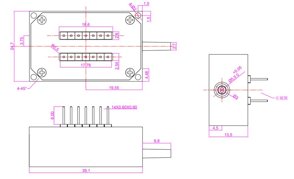
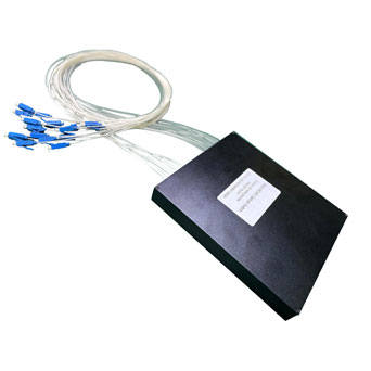
Dimension(MEMS 1x12/16/24/32/48 Optical Switch) of MEMS 1xN(2≤N≤48) Optical Switch Module
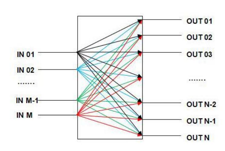
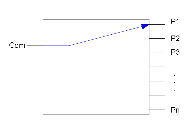
Principle of Optical Path Switching of MEMS 1xN(2≤N≤48) Optical Switch Module
The optical 1xN switch is a non-locking product. When the voltage is removed, the mirror returns to the initial position and the input is uncoupled to any output channel. The principle of optical path switching is shown in figure below.
Order Information of MEMS 1xN(2≤N≤48) Optical Switch Module
OE-MS-1×N-A-B-C-D-E-F-G (MS: MEMS Optical Switch)
N | A | B | C | D | E | F | G |
Output Number | Fiber Type | Package Type | Test Wavelength | Tube Type | Fiber Length | Connector | Control InterFace |
2:2 4:4 8:8 12:12 16:16 24:24 32:32 48:48 | SM:SM,9/125 X:Others | M1:Modules-1 M2:Modules-2
| 1310:1310nm 1550:1550nm 1315:1310&1550nm | 25:250um 90:900um X:Others | 05:0.5m±5cm 10:1.0m±5cm 15:1.5m±5cm X:Others | OO:None FP:FC/PC FA:FC/APC SP:SC/PC SA:SC/APC LP:LC/PC LA:LC/APC X:Others | TTL/RS232 TTL/ I2C TTL/I2C/RS232 |
Note:1. Above specifications just show the typical performance of Module.
2. Please contact our sales to discuss your specific requirements.

 EN
EN

